

T-110.5101 Laboratory Works on Datacommunications Software (5 cr)
Lab 6: Router
Literature
The following books can be read at or borrowed (for one night) from the library of the T-building:
- Cisco Certified Network Associate Study Guide
- CCNA Portable Command
General instructions
You need a USB stick for these labs. You’ll store the complete labs on your stick and delete them from the PC so that no other group can plagiarize your job.
If you mistype a command you can negate that by selecting the mistyped command with arrow keys, typing "cntl-a" to move the cursor into the beginning of the line and then type "no" and then Enter. Remember to use "?" command if you don't remember what to do. The question mark lists all the available commands and options.
When you get into a specific configuration mode, you'll get out by typing "exit". Or you can leave the configuration mode and return back to the privileged exec mode by typing cntl-z. Learn to use the arrow, tab and ‘?’ keys. Remember, you don’t have to type the whole commands, use tab and shortened commands diligently.
We use consistently the password "cisco" in these tasks, but this is not to be used in real life! Note that with the simulator when you apply a login command, you must type the password before login.
Preliminary task
A preliminary task is attached to this page as an Excel spreadsheet. Fill it in and return it together with your final configuration files.
Task 1: Basic Switch and Router Configuration
The first task presents the basic command set, that is invoked with all the Cisco switches and routers plus the port security command.
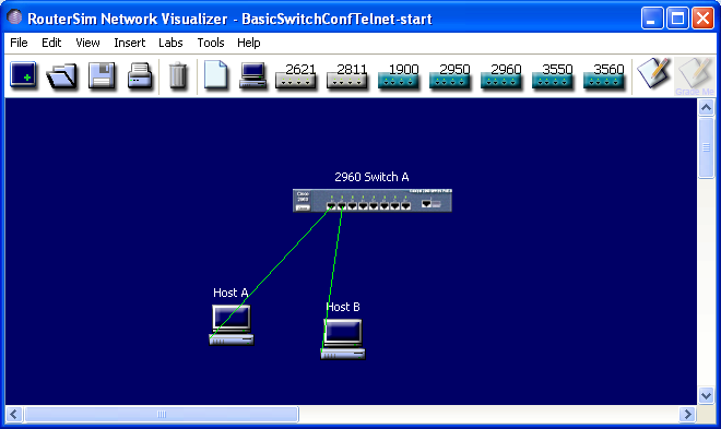
The starting point is a 2960 switch with a blank configuration and two connected PCs. Host A is connected into the f0/1 and is used to test the port-security. Host B is connected into the f0/2 and is used to test the telnet. Host A has blank IP settings (they are not needed) and host B has the following IP settings:
IP address: 10.0.0.3
Subnet mask: 255.255.255.0
Default gateway: 10.0.0.1
You can see the IP settings of a host by clicking with the right mouse button (RMB) the host and clicking with the LMB the command “Configs”.
The image of the starting network is below:
- With the left mouse button (LMB), click the command: "NetVisualizerScreen". A new window appears
- Open the file "#DIRECTORY#\#GROUP#\BasicSwitchConfiguration\BasicSwitchConfTelnet-start" with cntl-o or File->Open or clicking the open menu button
- Save the file right away with the name "#DIRECTORY#\#GROUP#\grp_n_BasicSwitchConfTelnet-end.rsm” (n is your group number) so you don’t accidentally write over the starting file. Cntl-s or File->Save or click the Save menu button
- Double-click the image 2960 Switch A on the canvas to get into the command line interface (CLI). Hit RETURN
- Get into the global configuration mode
- Change the switch name into "MY_SWITCH"
- The next step would be setting the clock, but this does not work with the simulator
- Set the encrypted secret password, which is required to get into the privileged exec mode. Choose the password "cisco"
- Set the login banner. Choose the text:
"Authorized personnel only!
Violators will be prosecuted
to the fullest extent of the law.” - The next step would be disabling DNS queries with "no ip domain-lookup" command, but this does not work with the simulator
- Set the console (0) login and password. Choose the password "cisco"
- The next step would be typing "logging synchronous" but this command does not work with the simulator
- The next step would be setting the idle time after which the console logs off, but this does not work with the simulator
- Set Telnet password and login. Choose the password "cisco". Secure all the Telnet lines, that is the number of simultaneous Telnet sessions that are allowed. This depends on the switch/router model and can be found by typing ? in the place of the number of Telnet sessions
- Set the IP default gateway to "10.0.0.1"
- Configure and open VLAN 1 for a management VLAN. Set the IP address to: "10.0.0.2" and the subnet mask to: "255.255.255.0"
- Configure the fastethernet 0/1 interface as follows:
- description to "Link to Moscow"
- set the port into the access mode and set the VLAN number to 20
- enable port security
- set the maximum number of hosts connected to this interface to 1
- set the port's MAC address sticky, that is, the switch learns the MAC address from the first host, that is connected into the switch
- set the action after a port-security violation to be shutdown (after the shutdown, the administrator must open the port with "no shut" command). OBS! "switchport port-security violation shutdown" command does not show on the configuration file. This is a bug in the simulator
- You don’t need to configure the fastethernet 0/2 if the port is used as an access port with VLAN 1, since this is the default setting for all unconfigured switch ports
- Return to the privileged exec mode by typing cntl-z, or exit twice. View your running configuration and check that everything is in place
- Copy running-configuration into startup-configuration
- Double-click the host B to open the DOS window. Open a telnet connection to the switch interface VLAN 1. Check that the both passwords are correct and take you into the privileged exec mode. You should be able to telnet from the host B into the switch and be able to view the running configuration. You will demonstrate these in the demo session
- View the running-configuration and check that the MAC address of the host A has appeared into the port f0/1. Then close the DOS window
- When everything works, save the file by cntl-s or from the menu: File->Save or by clicking the Save menu button. Use the name: "#DIRECTORY#\#GROUP#\grp_n_BasicSwitchConfTelnet-end.rsm", where n is your group number
- Store the complete lab “grp_n_BasicSwitchConfTelnet-end.rsm” in your USB stick and then delete it from the PC
Grading:
| Telnet succeeds from Host B to the switch | 1p |
| Login banner shows | 1p |
| Both the passwords (cisco) take you into the privileged exec mode | 1p |
| “MY_SWITCH#sh run” shows the correct config for the interface f0/1 | 1p |
| “MY_SWITCH#sh run” shows the default IP gateway correctly | 1p |
Task 2: VLAN and Router-on-a-Stick
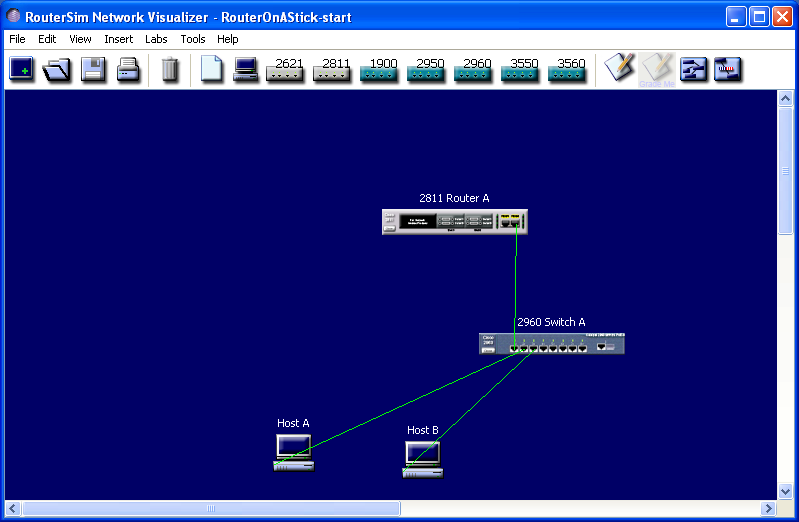
The second task presents the basic L2/L3 configurations. The purpose is to configure one switch and one router, which follow the so-called router-on-a-stick configuration. There are 2 VLANs and additionally 1 management VLAN. Both VLANs have one host (PC) connected to it and with the help of a router and a switch an inter-VLAN routing is configured. The configuration is complete when you can ping between the PCs. The management VLAN is not tested, but it needs to be configured as well to get points.
The starting network has one router, one switch, 2 hosts and wiring between the devices. The host IP settings are preconfigured, so you have to configure only the switch and the router.
Host A
IP address 172.16.10.2
Subnet 255.255.255.0
Default gateway 172.16.10.1
Host B
IP address 172.16.20.2
Subnet 255.255.255.0
Default gateway 172.16.20.1
The image of the starting network is below:
- Open the initial network "#DIRECTORY#\#GROUP#\RouterOnAStick\RouterOnAStick-start.rsm"
- At first, save the initial network with the name: "#DIRECTORY#\#GROUP#\grp_n_RouterOnAStick-end.rsm", where "n" is your group number. You do all the configs into this file
- Start by configuring the switch. Double-click the switch on the canvas and hit RETURN
- Get into the global configuration mode
- Create 2 VLANs. The first has the VLAN id (number) 10 and the name Production. The second has the VLAN id (number) 20 and the name Finance. Check the created VLANs with an appropriate command
- Configure the interface f0/1 into the trunk port
- Configure the interface f0/2 into the access port and for VLAN 10
- Configure the interface f0/3 into the access port and for VLAN 20
- Create and open the interface VLAN 1 and assign the IP address 172.16.1.2 with the net mask 255.255.255.0
- Return to the privileged exec mode
- View the created configuration and copy running-configuration into start-configuration
- Close the config window of the switch
- Save the intermediate result with the name "#DIRECTORY#\#GROUP#\grp_n_RouterOnAStick-end.rsm", where "n" is your group number
- Then configure the router. Double-click the router on the canvas and hit RETURN
- Get into the global configuration mode
- Configure and open the physical interface f0/0. Assign no ip address
- Configure the subinterface f0/0.1. Give it the description "Management", configure the encapsulation into dot1q with the VLAN id 1. Assign the IP address 172.16.1.1 with a net mask 255.255.255.0
- Configure the interface f0/0.10. Give it the description "Production", configure the encapsulation into dot1q with the VLAN id 10. Assign the IP address 172.16.10.1 with a net mask 255.255.255.0
- Configure the interface f0/0.20. Give it the description "Finance", configure the encapsulation into dot1q with the VLAN id 20. Assign the IP address 172.16.20.1 with a net mask 255.255.255.0
- Return to the privileged exec mode and view the running configuration to check that everything is in place
- Save running-configuration into start-configuration
- Double-click the left-side PC to open the DOS window and ping the right-side PC. After a successful ping, close the DOS window. Ping also the other way around. Double-click the right-side PC to open the DOS window and ping the left-side PC. Note, that to get maximum points in this task, a successful ping in both directions is required. You will demonstrate this in the demo session. Also you must show the configuration in both the switch and the router to demonstrate that VLAN 1 is in place
- When everything works, save the final result with the name "#DIRECTORY#\#GROUP#\grp_n_RouterOnAStick-end.rsm"
- Store the complete lab “grp_n_RouterOnAStick-end.rsm” in your USB stick and then delete it from the PC
Grading
| A successful ping from Host A to Host B | 1p |
| A successful ping from Host B to Host A | 1p |
| “Switch#sh run” shows a correct configuration for VLAN 1 | 1p |
| “Router#sh run” shows a correct configuration for VLAN 1 |
1p |
Task 3: Routing and ACL
The third task presents the basic L3 configurations and the access control list. The purpose is to first configure a small network with static routes, then apply RIPv2 and finally configure ACL (Access Control List). The static and dynamic routes can co-exist within the same router, but this is not applicable with the simulator, because it does not recognize the administrative distance option (which tells, which route is preferred over the other).
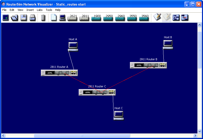
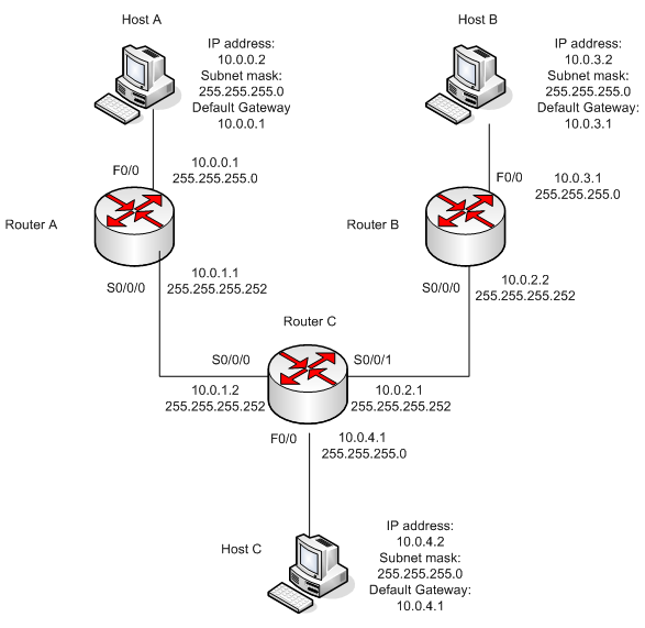
The starting network has 3 routers each connected to one PC. The wiring and the IP settings of PCs are preconfigured, so you only have to configure the routers, which have a blank configuration. Two of the routers will be configured with all the IP routes and one router will be configured with a default route. The configuration is complete when you can ping between all the PCs.
The simulator image of the starting network is below:
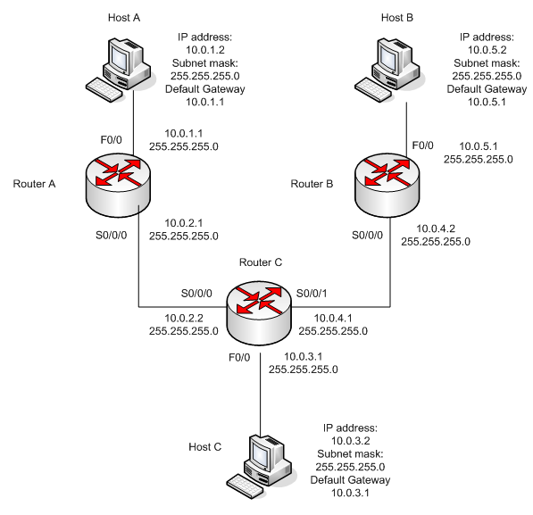
The network settings are described below:
STATIC ROUTES
- Open the initial network "#DIRECTORY#\#GROUP#\Routing\Static_routes-start.rsm"
- At first, save the initial network with the name: "#DIRECTORY#\#GROUP#\grp_n_Static_routes-end.rsm", where "n" is your group number. You do all the configs into this file
- You must be able to ping the router interface before you add a route (this is not necessarily true with the simulator). This is why we first connect all the direct connections of the 3 routers. Remember to open all the router interfaces after configuring them
- Start with the router 2811 Router A. Double-click the router on the canvas and hit RETURN. Configure the interfaces f0/0 and s0/0/0 with the IP settings of the image above. Save the running-configuration
- Then move to the router 2811 Router C. Double-click the router on the canvas and hit RETURN. Configure the interfaces f0/0, s0/0/0 and s0/0/1 with the IP settings of the image above. Save the configuration
- Move to the router 2811 Router B. Double-click the router on the canvas and hit RETURN. Configure the interfaces f0/0 and s0/0/0 with the IP settings of the image above. Save the configuration
- Start the static route configuration with the 2811 Router A. Double-click the router on the canvas and hit RETURN. There are 3 networks, you must configure according to the image above. Save the configuration
- Then move to the router 2811 Router C. Double-click the router on the canvas and hit RETURN. There are 2 networks, you must configure. Save the configuration
- Finally move to the router 2811 Router B. Double-click the router on the canvas and hit RETURN. You only configure the default network. Remember to give a command “Router(config)#ip classless”. Save the configuration
- Check the configuration with “show ip route” command in each of the routers. When you are done, ping from all the PCs to other two PCs. Double-click the PC on the canvas and type: “C:\>ping 10.0.3.2” etc.
- The configuration is complete when you can ping between all the PCs. You will demonstrate these in the demo session
- When everything works, save the final result with the name "#DIRECTORY#\#GROUP#\grp_n_Static_routes-end.rsm"
- Store the complete lab “grp_n_Static_routes-end.rsm” in your USB stick and then delete it from the PC
Static route grading:
| A successful ping between the PCs | 1p |
RIP
The initial network of RIP is described below. All the directly connected router interfaces and the IP settings of each PC are preconfigured, so you only have to configure the RIPv2 routing for the routers. The configuration is complete when you can ping between all the PCs. This is graded passed/failed.
- Open the initial RIP network "#DIRECTORY#\#GROUP#\Routing and ACL\RIP-start.rsm"
- At first, save the initial network with the name: "#DIRECTORY#\#GROUP#\grp_n_RIP-end.rsm", where "n" is your group number. You do all the configs into this file
- Next, double-click each of the routers and submit the RIPv2 settings. Remember, you only need to supply classful networks (A, B or C), not subnetted networks (classless). Apply RIPv2 and turn off the auto-summary in each of the routers
- When everything is in place, check the networks with “show ip route” command. You should see each of the subnets, both the directly connected and routed networks. Because you turned off the auto-summary, all the subnets are listed here
- The configuration is complete when you can ping between all the PCs. You will demonstrate these in the demo session
- When everything works, save the final result with the name "#DIRECTORY#\#GROUP#\grp_n_RIP-end.rsm"
- Store the complete lab “grp_n_RIP-end.rsm” in your USB stick and then delete it from the PC
What is the subnet, broadcast address and host address range for the subnet between Router A and Router C? You can use the on-line tool http://www.subnet-calculator.com/. Obs! If you cannot subnet in your head, you need a tool like this. You will present the answer in the demo session
RIP and subnet grading:
| A successful ping between the PCs |
2p |
| A correct subnet answer | 1p |
ACL
In this assignment you create 2 extended ACLs for a corporate network. The image of the network is below. Note that because of the absence of firewalls and a NAT box, the network is not very practical. The corporate network contains one gateway router (Router B), which is connected to the ISP router (Router A, which lies on the premises of the ISP, so you don’t have an access to this router), one internal router (Router C), one switch, 2 PCs, one of which is a management PC and a Web Server. The internet contains an ISP router and a PC.
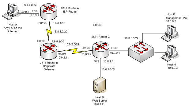
The network and PC settings and routing (static) are preconfigured so you only have to create 2 extended ACLs and activate them on the appropriate interfaces. Remember the 2 rules for the ACL placement:
#1 Standard ACLs should be placed as close to the destination as possible
#2 Extended ACLs should be placed as close to the source as possible
Please note, that there are some limitations in the simulator regarding the ACL syntax. If needed, check the supported commands in: http://www.routersim.com/CCNA6_Supported_Commands.html#2811%20RouterGlobal%20Config
The image of the simulator window is below:
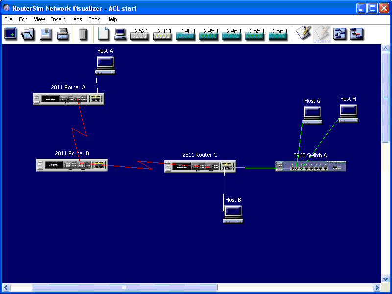
In the initial situation, all the PCs can ping each other.
- Open the initial ACL network "#DIRECTORY#\#GROUP#\Routing and ACL\ACL-start.rsm"
- At first, save the initial network with the name: "#DIRECTORY#\#GROUP#\grp_n_ACL-end.rsm", where "n" is your group number. You do all the configs into this file
#1 ACL
This ACL controls the access to the Web Server from the intranet. Use the ACL number 100.
Following the #2 rule, create the extended ACL number 100 into the appropriate router, an appropriate interface and an appropriate direction (in/out).
Double-click the router of your choosing and enter into the global configuration mode.
- The first statement allows all the IP traffic from the management PC (Host G) to the corporate Web Server. Use the syntax:
- Router(config)#access-list 100 permit ip host source_IP_address destination_IP_address destination_wildcard_mask
- The second statement allows only HTTP-TCP traffic from the host H to the corporate Web Server. Use the syntax:
- Router(config)#access-list 100 permit tcp host source_IP_address destination_IP_address destination_wildcard_mask eq 80
- The third statement denies all the IP traffic from the subnet 10.0.0.0/24 to the subnet 10.0.1.0/24. Use the syntax:
- Router(config)#access-list 100 deny ip source_subnet wildcard_mask destination_subnet wildcard_mask
- The fourth statement allows all the IP traffic. Use the command:
- Router(config)#access-list 100 permit ip any any
- Finally, activate the ACL for the interface and save the configuration.
Now you should be able to ping from Host G to the Web Server (10.0.1.2). You should not be able to ping from Host H to the Web Server. You should be able to ping from Host H to the internet, that is 9.9.9.2. You will demonstrate this in the demo session
When everything works, save the result with the name "#DIRECTORY#\#GROUP#\grp_n_ACL-end.rsm"
#1 ACL grading:
| A successful ping from Host G to the Web Server (10.0.1.2) |
1 |
| A failed ping from Host H to the Web Server | 1 |
| A successful ping from Host H to the Internet (9.9.9.2) | 2 |
#2 ACL
This ACL controls the access from the Internet to the intranet. The traffic originating from the Internet has an access only to the corporate Web Server. Following the #2 rule, create the extended ACL number 110 into the appropriate router and an appropriate interface
Double-click the router of your choosing and enter the global configuration mode.
- The first statement allows only HTTP-TCP traffic from the Internet (any source IP address) to the corporate Web Server. Use the syntax:
- Router(config)#access-list 110 permit tcp any destination_IP_address destination_wildcard_mask eq 80
- There should be no second statement, but in order to be able to test this ACL, a second statement is created. Allow ICMP traffic from the Internet (any source IP address) to the corporate Web Server. Use the syntax:
- Router(config)#access-list 110 permit icmp any host destination_IP_address
- Finally, activate the ACL for the interface and save the configuration.
- Now you should be able to ping from host A to the Web Server. You should not be able to ping from Host A to Host G. You will demonstrate these in the demo session.
- When everything works, save the result with the name "#DIRECTORY#\#GROUP#\grp_n_ACL-end.rsm", copy it to your USB stick and then delete it from the PC
#2 ACL grading:
| A successful ping from Host A to the Web Server |
1p |
| A failed ping from Host A to Host G | 1p |
Task 4: NAT and DHCP
The fourth task presents the PAT and DHCP configurations. The network to start with has one corporate gateway router. You will configure this router as a DHCP server and a NAT box (Port address translation). The configuration is complete when you can demonstrate, that Host A and Host B have received dynamic IP settings and you can ping from Host A and from Host B to Host C but not the other way around. Also you have to demonstrate the DHCP and NAT configurations with a command: “Router#sh run”. The IP settings, interfaces and routing (partial – no route from ISP Router to 10.0.0.0/24 has been configured, since this will be a private network) have been preconfigured. Also the Host A and Host B have been configured to get dynamic IP address. So your job is only to configure the corporate gateway router.
The simulator image of the starting network is below:
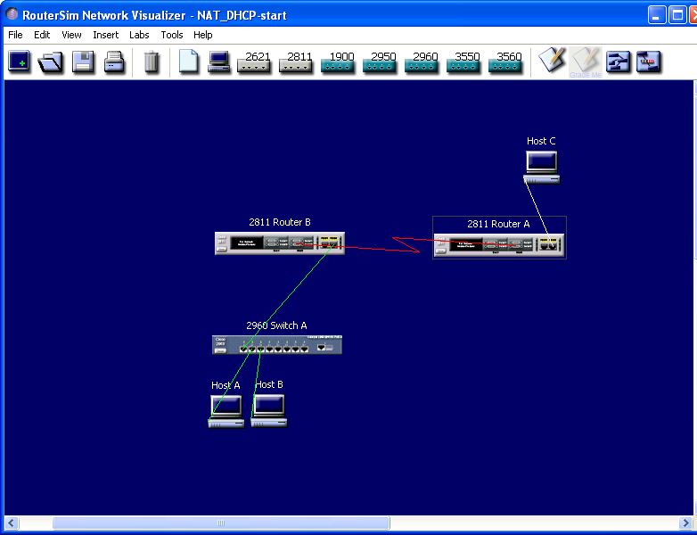
- Open the initial network "#DIRECTORY#\#GROUP#\NAT_DHCP\NAT_DHCP-start.rsm"
- At first, save the initial network with the name: "#DIRECTORY#\#GROUP#\grp_n_NAT_DHCP-end.rsm", where "n" is your group number. You do all the configs into this file
- Configure the following parameters of the DHCP server within the router B (Corporate Gateway Router).
- pool name “cisco”
- network 10.0.0.0 255.255.255.0
- DNS server 60.60.60.1
- default router 10.0.0.1
- lease time 1 day 0 hours 0 minutes
- domain name mydomain.com
- excluded IP addresses are 10.0.0.1-10.0.0.10. Please note, that you can invoke this command, but it does not have an effect. This is a bug in the simulator
- Verify that Host A and Host B receive their IP settings by double-clicking them and typing “C:\>ipconfig”. Please note, that you cannot ping from the Host A or B to Host C, since there is no route to the subnet 10.0.0.0/24. You will demonstrate in the demo session that Host A and Host B have received dynamic IP addresses.
- Next, configure the PAT. Use the pool name “cisco”. Use the public IP address 200.200.2.2/24, the list number 1 and permit access to the subnet 10.0.0.0/24. The configuration is complete when you can ping from the Host A and Host B to the Host C but not the other way around. Also, you have to demonstrate the DHCP and NAT configurations with “Router#sh run” command. Double-click the Router B and enter the global configuration mode. Then, configure the PAT. Finally, save the configuration.
- When everything works, save the final result with the name "#DIRECTORY#\#GROUP#\grp_n_NAT_DHCP-end.rsm"
Store the complete lab “grp_n_NAT_DHCP-end.rsm” in your USB stick and then delete it from the PC
Grading:
| Host A and Host B have received their dynamic IP addresses | 2p |
| A successful ping from Host A and Host B to Host C |
2p |
| A failed ping from Host C to Host A and Host B | 2p |
| “Router(B)#sh run” shows a correct DHCP and NAT configurations |
2p |
|
|
|||
|---|---|---|---|---|
| preliminary | Preliminary exercise. Fill in this file and submit together with your configuration files. | |||
| documentation | Powerpoint presentation containing the necessary documentation for the assignment. | |||
| configuration | Initial configuration files for the exercises. | |||